Implement according to the project list
Confirm the scope of CNC machine tools, robots, punches, PLC, frequency converters, power distribution rooms, air compressors and energy metering equipment according to the project equipment list.
For CNC, robots, PLC, instrument testing and energy equipment, confirm the access method by type and promote on-site construction.
Confirm the scope of CNC machine tools, robots, punches, PLC, frequency converters, power distribution rooms, air compressors and energy metering equipment according to the project equipment list.
Unify field definitions such as equipment status, alarms, programs, coordinates, output, energy consumption, etc., and record field sources and collection conditions.
Direct network port acquisition, serial port conversion to Ethernet, or the installation of an IO/power meter can be used, depending on the equipment conditions.
Complete parameter configuration, hardware installation and communication debugging simultaneously, and check the on-site results according to the agreed acceptance items.
Prioritize communication conditions and implement them in three categories: direct access to network port devices; access to serial port devices through protocol conversion gateways; additional IO or smart meter collection for devices without interfaces.
During implementation, complete network parameter configuration and data point verification, focusing on collecting fields such as power on/off, status, alarms, programs, processing time, output, spindle/feed, coordinates, and load.
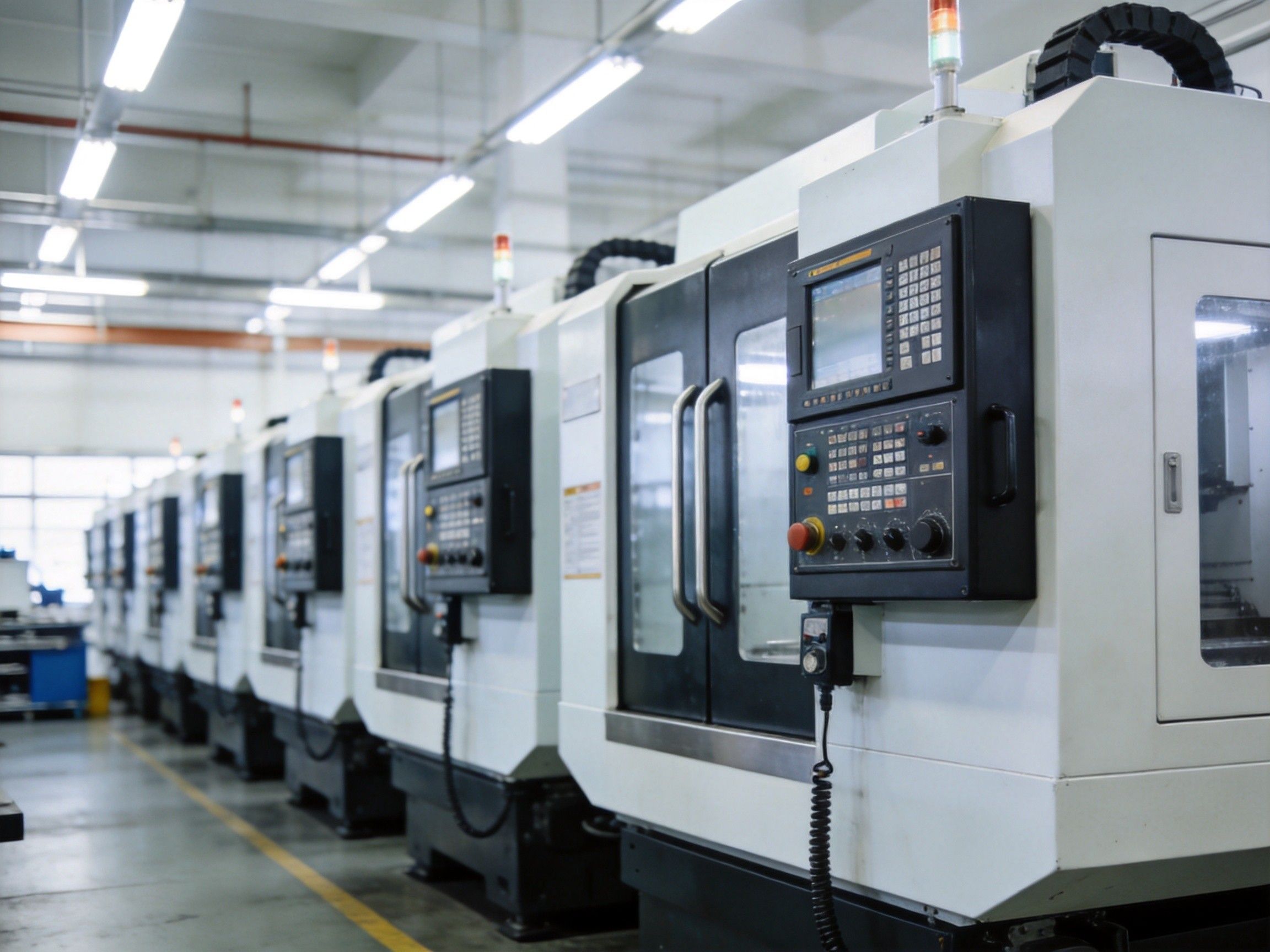
Establish a data channel according to the controller communication protocol, first covering status, emergency stop, alarms, and mode signals, then jointly debugging program status and alarm details.
On the motion data side, focus on J1-J6 joint coordinates and user/world coordinates to create a traceable data chain for cycle, exceptions, and process.

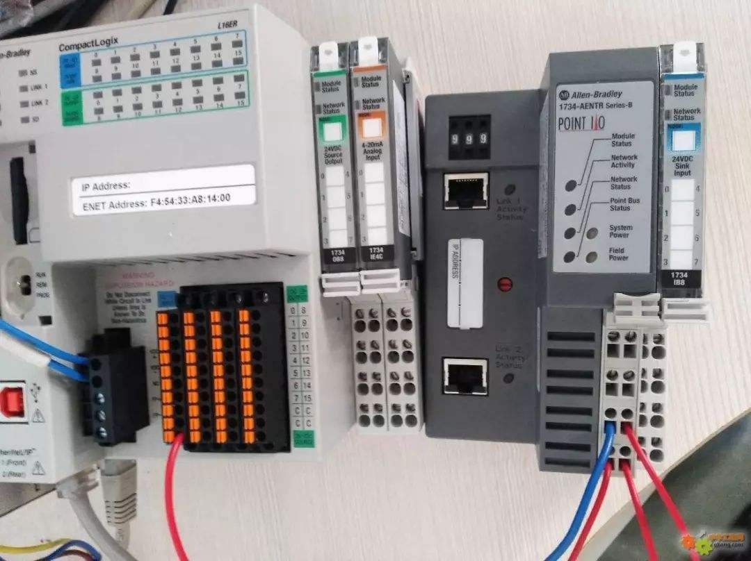
Carry out implementation based on PLC tag tables and key touchscreen parameters: networked devices are directly acquired, serial-port occupied scenarios are converted via extended gateways before integrating into the platform.
Focus on checking status, alarm, temperature, pressure, time, weight and other process fields on site, and check point naming, dimensions and sampling cycle.
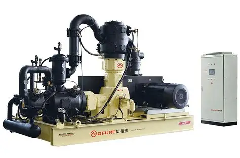
Air compressors collect pressure, temperature, load duration, and energy consumption via RS485; cranes and hoisting equipment use industrial LoRa wireless communication; testing equipment collects inspection result data.
Energy meters for water, electricity, and gas are connected via Modbus, with device addresses, communication quality, and measurement accuracy verified during implementation.
Output equipment register, protocol types, acquisition fields, and priorities; clarify categorization of network, serial, and interface-less devices.
Networked machines: wiring and parameter configuration; serial machines: add protocol converters; interface-less devices: install IO hardware and complete 24V power supply.
Complete debugging of device status, alarms, output, process, and energy fields; verify data completeness, timing, and consistency.
Organize gateway configuration, point list and construction work records to facilitate subsequent maintenance; new equipment needs to recheck the agreement and point location.
After providing the equipment list and target scenarios, we can output implementation plans, construction checklists, joint debugging steps, and acceptance criteria by chapter.